MAXIPOL Focal Plane
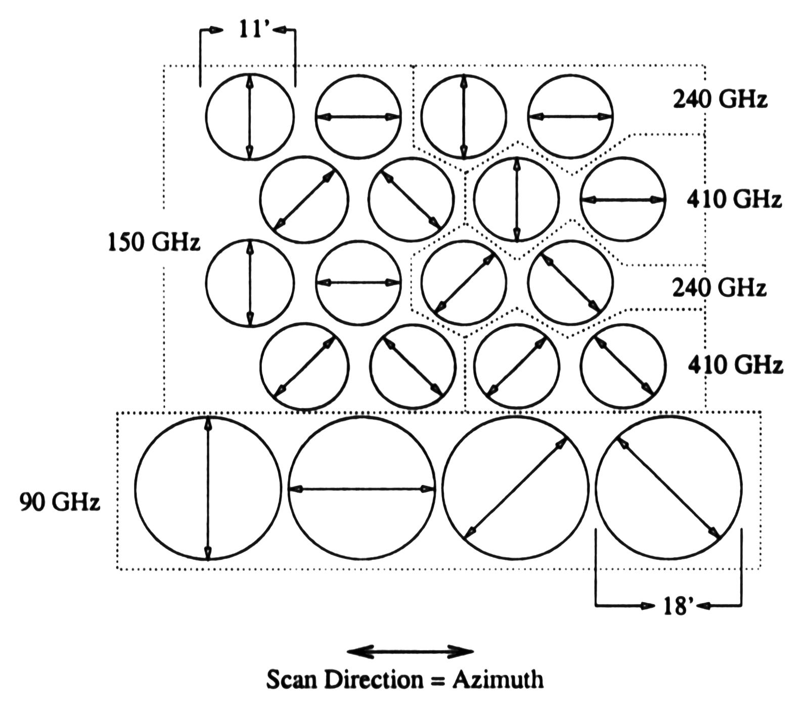
MAXIPOL will measure polarized intensities by using polarizing wire grids at the entrance apertures of the horns on the focal plane. The focal plane layout of the polarimeter is shown above. It consists of 20 single-frequency photometers distributed among four frequency bands. Each photometer measures only the intensity of a single linear polarization component of the incident radiation field. Four components, at angles -45, 0, 45, and 90 degrees with respect to local elevation are measured at each frequency band. The Q and U Stokes parameters are extracted by differencing two photometers mounted directly adjacent to one another in azimuth which have orthogonal polarizing grids (Q and U are formed from the 0 and 90 degree pair, and 45 and -45 degree pair, respectively). These two photometers measure the same sky pixel in rapid succession as the focal plane is scanned across the sky in azimuth. The temperature signal is obtained by adding the signals from two adjacent photometers, rather than differencing them. Since these are total power scans, we will obtain sky maps of the anisotropy in Q and U, as well as of the temperature anisotropy.