![]()
largely based on the thesis of Michael J. Krueger
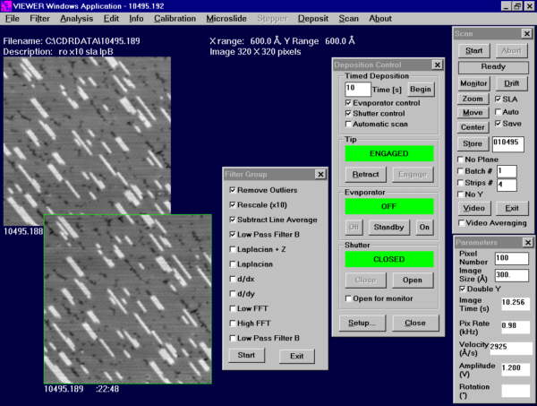
FIG. 1. Screen shot of the Viewer application. On the left are two STM images acquired with Viewer, int the center is a menue bar of filtering options, beside it is the control pannel for an evaporator, and on the right are the image acquisition controls.
Viewer is the 16-bit Windows application that controls the STM electronics and allows the user to acquire, view, process, store, and retrieve STM images. Viewer began its life as a MS-DOS program for STM control developed at Harvard by Eric Ganz from 1988–1991. At the University of Minnesota, Viewer was ported to 16-bit Windows by Eric Ganz and Peter Gaard in 1992. In 1993 it was modified to fit within the framework of the Microsoft Foundation Classes (MFC) for the 16-bit version of Microsoft Visual C++, and was further improved by Peter Gaard and Xin Shi. A screen shot of Viewer’s user interface is shown in Fig. 1.
With the departure of Peter Gaard and Xin Shi, Michael Krueger assumed responsibility for the maintenance and improvement of Viewer. He made a number of modifications and improvements to the application. Two of the most significant additions to Viewer were support for the atom tracker and a real-time video display mode for the fast STM instrument.
Analysis
With the arrival of 32-bit opporating systems (Windows 95 and NT), and the expanding role of Viewer in image analysis, it became desirable to create a 32-bit annalysis program. It duplicates much of the analysis capabilities of Viewer, adds image rotation and skewing, point FFT filter and the ability to compile, view, and filter series of STM images. Analysis may, someday, take over the acquisition role and completely replace Viewer.
A useful feature of Analysis not found in Viewer
is the point fast Fourier transform (FFT) filter. An STM
image can be displayed simultaneously in real and reciprocal
space. Because the x and y scan speeds are
constant during the acquisition of an image, electrical noise and
mechanical resonances appear as sharp maxima in the 2-D FFT of
the STM height data. In point FFT filter mode, the user is
able to remove a noise peak from the reciprocal point ![]() by clicking on it with the mouse,
causing the filter term [1 + (k/K)2]-n,
where
by clicking on it with the mouse,
causing the filter term [1 + (k/K)2]-n,
where ![]() , and K and n are specified
by the user, to be subtracted from each point
, and K and n are specified
by the user, to be subtracted from each point ![]() in the reciprocal-space image.
Because only the periodic noise components are removed, this
filtering technique produces dramatic results that cannot be
obtained with simpler low-pass filtering methods.
in the reciprocal-space image.
Because only the periodic noise components are removed, this
filtering technique produces dramatic results that cannot be
obtained with simpler low-pass filtering methods.
 |
|
Fig. 3 STM Movie. The series of images tiled on the left are compiled into a movie on the right. In this format, details of the dynamics are more easily observed.
Jump to
Hot STM Labs
Copyright 2000 by the Regents of the University of Minnesota